

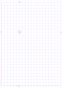
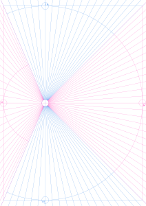
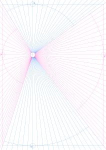
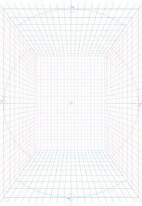
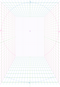
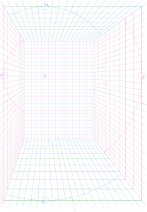
This is a collection of materials that allows you to freely determine the depth and draw the grid on four types of one-point perspective grids with different focus positions. 焦点位置の異なる4種の1点透視グリッドに、自由に奥行きを決めてグリッドを引くことの出来る素材集です。


 ≫≫
≫≫
 ≫≫
≫≫
 ≫≫
≫≫


 ≫≫≫≫≫≫
One-point perspective creation set 一点透視作成セット


Single point perspective grid 一点透視グリッド


Innermost Grid 最奥グリッド
-
A little perspective on the most mysterious (center) 一点透視最奥(中心)
-
One-point perspective innermost [vertical] 一点透視最奥【縦】
-
One-point perspective innermost [horizontal] 一点透視最奥【横】
-
A little perspective on the most mysterious (corner) 一点透視最奥(角)
-
One-point perspective (common) innermost grid 一点透視(共通)最奥グリッド
-
A little perspective (common) the most mysterious "Focus" 一点透視(共通)最奥《焦点》


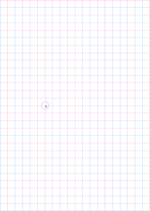


Depth Grid 奥行きグリッド


Frequency Count Scale 線数カウントスケール


【Sample】 【Sample】


Other materials by 渡季


Popular “Material catalog” materials


New materials


-
 MVP ◆This user has contributed greatly to the management of the community, by posting many great responses to the questions asked. Once every three months, MVPs are determined based on the points earned during that period and will be recognized accordingly.
 -
 New Valuable Player (NVP) ◆These are the next-best contributors to the community after MVPs. This is awarded to users who have not yet won an MVP award, based on the number of points they have earned.
 -
 Official Expert ◆Chosen out of all MVP awardees, who are already proof of excellence, this is a testimony of outstanding correspondence in the community. After careful screening, they are appointed by CELSYS and assume their position.Note: Formally called “Evangelists”
 -
 Official Moderator of CELSYS ◆Moderators are official CELSYS staff members who are fluent in Japanese as well as various other languages. Moderators are not experts on the software or illustration, so they are not able to directly answer your questions. However, moderators provide communication and language support to ensure that everyone can smoothly communicate with each other.
 -
 CELSYS official accountThe Official Administrator Account